
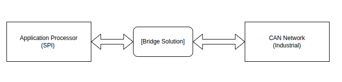
Most modern application processors, Raspberry Pi CM4, i.MX6, Allwinner H6, lack CAN controllers. The economics are straightforward: consumer volumes dwarf industrial applications, so mainstream SoC vendors optimize for WiFi and USB, not CAN. But industrial control and automotive systems still run on CAN bus, leaving you needing to bridge SPI to CAN.
This post covers three approaches I've worked with for implementing SPI-to-CAN bridges, their tradeoffs, and practical considerations for each.
Three Approaches
Every modern processor has SPI. Very few have CAN.
You have three options:
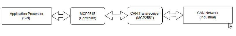
- Buy a dedicated SPI-to-CAN controller IC (MCP2515, TCAN4550)
- Roll your own bridge using an MCU with native CAN (STM32, etc.)
- Hybrid approach for multi-network setups
Let's look at each.
Dedicated Controller IC Approach
MCP2515: The Established Option
The MCP2515 was introduced in 2005. It's widely used in hobbyist and low-cost industrial projects.
Specs:
- 5 message buffers total (3 TX, 2 RX)
- Classical CAN only (8-byte frames, no CAN-FD)
- 1Mbps max bit rate
- 10MHz SPI clock max
- Needs external transceiver and crystal
Hardware Connection
Basic usage:
// Load message into TX buffer
spi_write(MCP2515_LOAD_TX_BUFFER, can_message);
spi_write(MCP2515_RTS_TXB0);

// Wait for interrupt
while (!interrupt_pin_active()) { delay_us(10); }

// Read received message
received_message = spi_read(MCP2515_READ_RX_BUFFER);
The limited buffer count means throughput around 3,000 messages/sec in typical implementations before buffer overflows occur. This works well for industrial sensor monitoring, but may not be sufficient for high-traffic automotive diagnostic scenarios.
TCAN4550: A Modern Alternative
The TCAN4550 addresses several limitations of the MCP2515 with increased buffer capacity and CAN-FD support.
Specs:
- 224 message buffers (32 TX, 64 RX, 128 FIFO)
- 2KB message RAM with ECC
- CAN-FD support (64-byte frames, up to 8Mbps)
- 18MHz SPI clock
- Built-in transceiver, no external components
- Internal oscillator option
Buffer Architecture Comparison:
| Feature | MCP2515 | TCAN4550 | Improvement |
|---|---|---|---|
| TX Buffers | 3 | 32 + 64 FIFO | 32x |
| RX Buffers | 2 | 64 + 64 FIFO | 64x |
| Message RAM | ~70 bytes | 2048 bytes | 29x |
| Max Frame Size | 8 bytes | 64 bytes | 8x |
| Throughput | 3K msg/sec | 25K msg/sec | 8.3x |
The larger buffer architecture enables sustained throughput in the range of 25,000 messages/sec. The buffer pool helps handle burst traffic that could overflow smaller buffer implementations.
For applications requiring CAN-FD or higher throughput (above 5K messages/sec), the TCAN4550 is often a better fit than the MCP2515.
Custom MCU Bridge
For applications requiring multiple CAN networks, custom protocol translation, or higher throughput, a custom microcontroller-based bridge may be appropriate.
MCU Selection
STM32 microcontrollers are commonly used for this, they're cost-effective, well-documented, and many variants include CAN controllers.
| MCU | Core | Freq (MHz) | SRAM (KB) | CAN Controllers | Max Throughput | Cost ($) |
|---|---|---|---|---|---|---|
| STM32F103 | M3 | 72 | 20 | 1 Classical | ~5K msg/sec | 3 |
| STM32G474 | M4 | 170 | 128 | 2 CAN-FD | ~40K msg/sec | 6 |
| STM32H743 | M7 | 550 | 1024 | 2 CAN-FD | 150K+ msg/sec | 18 |
The F103 is an older, low-cost option suitable for simple bridges. The G474 offers dual CAN-FD controllers with more RAM for buffering at moderate cost. The H743 provides the highest performance for demanding applications like multi-network automotive test equipment.
Architecture
The key challenge is handling asynchronous traffic from both directions without losing messages. CAN interrupts fire whenever messages arrive, while SPI is polled by the host. This requires queues in both directions.
Data structures:
typedef struct {
    message_t buffer[BUFFER_SIZE];
    volatile uint16_t head, tail, count;
    uint32_t overflow_count;
} message_queue_t;

// Bidirectional message queues
message_queue_t spi_to_can_queue;
message_queue_t can_to_spi_queue;
Main loop:
void bridge_main_loop(void) {
    while (1) {
        // Check if host sent us something
        if (spi_message_available()) {
            message_t msg = spi_receive_message();
            queue_push(&spi_to_can_queue, &msg);
        }

        // Drain the CAN TX queue
        process_can_tx_queue();

        // CAN RX happens in interrupt, don't poll it
    }
}
CAN reception should be handled in interrupt context to minimize latency and prevent message loss during high traffic. SPI is typically polled since it's host-driven and has lower throughput requirements.
Buffer sizing is important. A common approach is 64-128 messages per queue for automotive applications, balancing memory usage against the need to handle traffic bursts.
Host-Side Implementation
The host processor needs to poll the bridge continuously, as SPI doesn't support interrupt-driven communication from the peripheral side.
Typical Linux implementation:
class CANBridge {
    bool transmitMessage(uint32_t id, const uint8_t* data, uint8_t len) {
        SPIFrame frame = {id, len, {0}, 0};
        memcpy(frame.data, data, len);
        frame.checksum = calculateChecksum(&frame);
        return spiTransaction(&frame);
    }

    void continuousPolling() {
        while (polling_active) {
            SPIFrame empty_frame = {0};
            SPIFrame rx_frame;

            if (spiTransaction(&empty_frame, &rx_frame)) {
                if (validateFrame(&rx_frame)) {
                    processReceivedMessage(&rx_frame);
                }
            }
            usleep(polling_interval_us);
        }
    }
};
Polling interval selection balances latency against CPU utilization. Typical intervals range from 2ms for high-traffic applications to 10ms for lower-traffic scenarios. Adaptive polling can optimize this tradeoff, though fixed intervals are simpler and adequate for many applications.
Multiple CAN Networks
Custom MCU bridges are well-suited for applications requiring multiple independent CAN networks running at different bit rates.
Per-network structures:
typedef struct {
    CAN_HandleTypeDef *handle;
    message_queue_t tx_queue;
    message_queue_t rx_queue;
    uint32_t bit_rate;
    bool network_active;
} can_network_t;

can_network_t networks[MAX_NETWORKS] = {
    {&hfdcan1, {0}, {0}, 500000, true},   // Powertrain CAN
    {&hfdcan2, {0}, {0}, 125000, true},   // Infotainment CAN
};
Each network has independent queues, bit rate configuration, and filtering rules. Message routing between networks is possible but requires careful design to prevent message storms or excessive bus loading.
Performance Comparison
Typical performance characteristics for each approach:
| Approach | Cost | Max Throughput | Latency | CAN Type | Networks |
|---|---|---|---|---|---|
| MCP2515 | $6-8 | ~3K msg/sec | 200-500µs | Classical | 1 |
| TCAN4550 | $8-12 | ~25K msg/sec | 50-100µs | CAN-FD | 1 |
| STM32G474 | $7-10 | ~40K msg/sec | 10-50µs | CAN-FD | 2 |
| STM32H743 | $18-25 | 150K+ msg/sec | 5-20µs | CAN-FD | 2+ |
Performance varies based on SPI clock speed, polling intervals, firmware implementation, and specific hardware configuration.
Common bottlenecks:
- Buffer overflows - Size buffers for burst traffic, not average traffic
- SPI overhead - Each transaction adds latency depending on clock speed
- Host CPU - Continuous polling impacts CPU utilization
- CAN bus physics - 1Mbps classical, 8Mbps CAN-FD data phase (theoretical max)
Which Approach to Use
Use MCP2515 when:
- You're building a hobby project or prototype
- Traffic is under 2K messages/sec
- You need classical CAN only
- Budget is tight
- You want something that just works with minimal setup
Typical applications: Industrial sensor monitoring, simple OBD-II readers, educational projects
Use TCAN4550 when:
- You need CAN-FD or want future compatibility
- Traffic is 5K-25K messages/sec
- You want an integrated solution (less BOM complexity)
- Timeline is tight, you don't want to write firmware
- Single network is sufficient
Typical applications: Automotive gateways, industrial IoT hubs, CAN-FD test equipment
Use Custom MCU when:
- You need multiple CAN networks simultaneously
- Traffic exceeds 25K messages/sec
- You need custom protocol translation or filtering
- You're integrating into an existing MCU-based product
- You need routing between networks or advanced message processing
Typical applications: Automotive test benches, multi-network gateways, high-performance data loggers, ECU simulators
Common Implementation Issues
Buffer Overflows
Buffer overflows are the most common failure mode. Bursts of CAN traffic can fill buffers faster than SPI can drain them.
Monitoring buffer utilization and implementing overflow handling is important:
void monitor_buffer_health(void) {
    uint16_t utilization = (buffer.count * 100) / BUFFER_SIZE;

    if (utilization > 75) {
        increase_polling_frequency();
        log_high_traffic_warning();
    }

    if (buffer.overflow_count > threshold) {
        implement_message_prioritization();
    }
}
SPI Synchronization
SPI timing requires careful attention to CPOL/CPHA settings and proper synchronization between master and slave. Sync bytes in the frame help detect communication issues:
// Example sync validation
static constexpr uint8_t CM4_TO_STM32_SYNC = 0xAA;
static constexpr uint8_t STM32_TO_CM4_SYNC = 0x55;

bool validateRxSync(const uint8_t* frame) {
    return frame[SYNC_OFFSET] == STM32_TO_CM4_SYNC;
}
CAN Bus-Off Recovery
CAN controllers enter "bus-off" state after excessive errors (error counter reaches 255). Proper recovery involves:
- Detecting bus-off condition via status register
- Stopping transmission
- Resetting the CAN controller
- Implementing backoff before rejoining the network
Summary
Decision guide:
- Low traffic, classical CAN only → MCP2515
- CAN-FD, moderate throughput → TCAN4550
- Multiple networks, high throughput, custom protocol handling → Custom MCU bridge
Performance range:
- 3K msg/sec (MCP2515) to 150K+ msg/sec (STM32H743)
- Latency from 5µs to 500µs depending on approach
Key considerations:
- Buffer sizing for burst traffic
- SPI synchronization and error handling
- CAN bus-off recovery mechanisms
- Polling interval vs CPU utilization tradeoffs
Select the simplest solution that meets your application requirements.
Additional Resources
Technical Documentation
- MCP2515 Datasheet - Microchip Technology Inc.
- TCAN4550-Q1 Datasheet - Texas Instruments
- STM32G4 Series Reference Manual - STMicroelectronics
- STM32H7 Series Reference Manual - STMicroelectronics
Application Notes
- CAN Bus Implementation Guide - Texas Instruments SLAAEJ3
- SPI Communication Best Practices - Microchip AN1426
- CAN-FD Protocol Implementation - Vector Informatik
- STM32 CAN-FD Configuration - STMicroelectronics AN5405
Evaluation Hardware
- MCP2515 CAN Controller Breakout - SparkFun development board
- TCAN4550EVM - TI evaluation module
- STM32 Nucleo Boards - Development platforms with CAN support
- Raspberry Pi CAN HAT - Various MCP2515-based add-on boards
Keep Reading
Related Articles
Comments
Sign in to join the discussion.
Loading comments…