Modern embedded systems frequently need to bridge the analog and digital worlds while providing immediate visual feedback. The combination of Analog-to-Digital Converters (ADC) and I2C displays creates a powerful foundation for real-time monitoring systems that appears across countless applications, from industrial process control to portable instrumentation.
The Core Concept
The architecture centers on continuous data flow: an ADC samples analog signals and converts them to digital values, while an I2C display presents this data in human-readable format. This pattern eliminates the need for external computers or complex interfaces, creating self-contained monitoring systems that operate independently.
Real-time feedback becomes possible without serial connections or external logging. Compact visualization fits into space-constrained applications while remaining cost-effective. The two-wire I2C interface minimizes wiring complexity, making the solution practical for both prototypes and production systems.
Understanding ADC Fundamentals
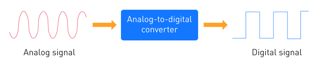
Every ADC performs the same fundamental operation: converting continuous analog voltages into discrete digital codes. Using a Raspberry Pi Pico as an example, the RP2040's 12-bit ADC demonstrates this relationship:
Digital Code = (Input Voltage / Reference Voltage) × (2^Resolution - 1)
With the RP2040's 3.3V reference:
- Output range: 0 to 4095 (2^12 - 1)
- Resolution: 3.3V ÷ 4095 ≈ 0.8mV per step
- Input of 1.65V produces: (1.65 ÷ 3.3) × 4095 ≈ 2047
Practical ADC Implementation
The RP2040 integrates a multi-channel ADC with internal voltage reference, simplifying portable designs. The conversion process in Zephyr RTOS looks like:
#include <zephyr/drivers/adc.h>

#define ADC_NODE DT_PHANDLE(DT_PATH(zephyr_user),io_channels)

const struct device *adc_dev = DEVICE_DT_GET(ADC_NODE);
struct adc_channel_cfg channel_cfg = {
    .gain = ADC_GAIN_1,
    .reference = ADC_REF_INTERNAL,
    .acquisition_time = ADC_ACQ_TIME_DEFAULT,
    .channel_id = 2, // GPIO28 on Pico
};

adc_channel_setup(adc_dev, &channel_cfg);

struct adc_sequence adc_sequence = {
    .channels    = BIT(ADC_CHANNEL),
    .buffer      = &sample_buf,
    .buffer_size = sizeof(sample_buf),
    .resolution  = ADC_RESOLUTION,
};

uint16_t raw_value;

adc_read(adc_dev, &adc_sequence, &raw_value);
float voltage = (raw_value / 4095.0f) * 3.3f;
Key technical factors include acquisition time, input impedance, and noise. The RP2040's ADC theoretically resolves ~0.8mV, but practical measurements include 2-3 LSB noise. Oversampling improves effective resolution:
uint32_t sum = 0;
for (int i = 0; i < 16; i++) {
    adc_read(adc_dev, &adc_sequence, &sample);
    sum += sample;
}
uint16_t averaged = sum >> 4; // Divide by 16
This technique smooths random noise, providing more stable readings across measurement cycles.
I2C Display Communication
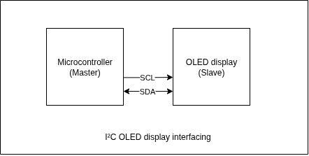
I2C OLED displays like the SSD1306-based 128×64 modules operate as slave devices responding to master microcontroller commands. They use only SDA (data) and SCL (clock) wires plus power connections. Most breakout modules include pull-up resistors, simplifying connections.
SSD1306 Controller Architecture
The SSD1306 stores screen contents in internal RAM and refreshes the OLED panel automatically. This architecture means your code only updates the buffer, the controller handles display timing independently.
Communication follows a standard pattern. Here is an example written in C:
// Assume i2c_write handles basic I2C transfer
#define OLED_ADDR 0x3C

void ssd1306_command(uint8_t cmd) {
    uint8_t buffer[2] = {0x00, cmd}; // Control byte 0x00 = command
    i2c_write(OLED_ADDR, buffer, 2);
}

void ssd1306_data(uint8_t *data, size_t len) {
    uint8_t control = 0x40; // Control byte 0x40 = data
    i2c_burst_prefix(OLED_ADDR, control, data, len);
}
The SSD1306 accepts both command sequences (for configuration) and data streams (for pixel content). Commands control contrast, addressing modes, and display power. Data transfers update the frame buffer content.
Display Initialization
The SSD1306 requires a specific initialization sequence before accepting display data:
void ssd1306_init() {
    ssd1306_command(0xAE); // Display OFF
    ssd1306_command(0x20); // Set memory addressing mode
    ssd1306_command(0x00); // Horizontal addressing mode
    ssd1306_command(0xB0); // Set page start address
    ssd1306_command(0xC8); // Set COM scan direction
    ssd1306_command(0x00); // Set low column address
    ssd1306_command(0x10); // Set high column address
    ssd1306_command(0x40); // Set start line address
    ssd1306_command(0x81); // Set contrast control
    ssd1306_command(0xFF); // Maximum contrast
    ssd1306_command(0xA1); // Set segment re-map
    ssd1306_command(0xA6); // Normal display mode
    ssd1306_command(0xA8); // Set multiplex ratio
    ssd1306_command(0x3F); // 1/64 duty
    ssd1306_command(0xAF); // Display ON
}
Once initialized, the display accepts character data, pixel arrays, or graphics commands through the same I2C interface.
Integration Implementation
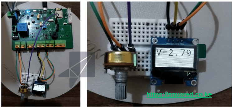
Combining ADC sampling with I2C display creates the monitoring loop. Using a 10K potentiometer connected to GPIO28 (ADC channel 2) on the Raspberry Pi Pico demonstrates the complete system:
void monitoring_loop() {
    char display_buffer[32];

    while (1) {
        // Sample ADC channel 2 (GPIO28)
        uint16_t adc_raw;
        adc_read(adc_dev, &adc_sequence, &adc_raw);

        // Convert to voltage
        float voltage = (adc_raw / 4095.0f) * 3.3f;

        // Format measurement text
        snprintf(display_buffer, sizeof(display_buffer),
                "ADC: %4d\nV: %.2fV", adc_raw, voltage);

        // Clear display area and write new data
        ssd1306_clear_region(0, 0, 128, 32);
        ssd1306_write_text(0, 0, display_buffer);

        // Update every 100ms
        k_msleep(100);
    }
}
This loop continuously samples the potentiometer, converts readings to voltage, formats the results as text, and updates the OLED display. The 100ms interval provides smooth visual updates while allowing time for other system tasks.
Zephyr RTOS Integration
Zephyr provides device tree configuration for both ADC and I2C peripherals. The device tree describes hardware connections:
&adc {
    status = "okay";
    #address-cells = <1>;
    #size-cells = <0>;

    channel@2 {
        reg = <2>;
        zephyr,gain = "ADC_GAIN_1";
        zephyr,reference = "ADC_REF_INTERNAL";
        zephyr,acquisition-time = <ADC_ACQ_TIME_DEFAULT>;
    };
};

&i2c0 {
    status = "okay";
    clock-frequency = <I2C_BITRATE_FAST>;

    ssd1306@3c {
        compatible = "solomon,ssd1306fb";
        reg = <0x3c>;
        width = <128>;
        height = <64>;
    };
};
This configuration enables Zephyr's driver framework to handle low-level peripheral initialization and provides standardized APIs for application code. You can check out the source code on github to see how we did the implementation.
Advanced Capabilities
Multi-Channel Monitoring
The RP2040 supports multiple ADC channels, enabling simultaneous monitoring of different sensors:
typedef struct {
    uint8_t channel;
    char label[16];
    float scale_factor;
    uint8_t display_line;
} sensor_channel_t;

sensor_channel_t sensors[] = {
    {0, "Temperature", 0.1f, 0},  // GPIO26
    {1, "Pressure", 1.0f, 1},    // GPIO27
    {2, "Voltage", 1.0f, 2},     // GPIO28
};

void multi_channel_monitoring() {
    for (int i = 0; i < ARRAY_SIZE(sensors); i++) {
        uint16_t raw;
        adc_read_channel(sensors[i].channel, &raw);
        float value = (raw / 4095.0f) * 3.3f * sensors[i].scale_factor;

        char text[32];
        snprintf(text, sizeof(text), "%s: %.2f",
                sensors[i].label, value);
        ssd1306_write_line(sensors[i].display_line, text);
    }
}
Graphics and Trends
Beyond text display, the SSD1306 supports pixel-level graphics for trend visualization:
void draw_trend_graph(float *values, int count) {
    // Clear graph area
    ssd1306_clear_region(0, 32, 128, 32);

    // Draw trend line
    for (int i = 1; i < count; i++) {
        int x1 = (i - 1) * 128 / count;
        int y1 = 63 - (values[i-1] / 3.3f) * 32;
        int x2 = i * 128 / count;
        int y2 = 63 - (values[i] / 3.3f) * 32;

        ssd1306_draw_line(x1, y1, x2, y2);
    }
}
This creates visual trends showing measurement history, making patterns and changes immediately apparent.
Implementation Considerations
Performance Optimization
Update rates balance responsiveness with power consumption. The example uses 100ms intervals, but applications may require faster sampling for dynamic signals or slower updates for battery life.
Interrupt-driven sampling can improve timing accuracy:
void adc_timer_handler() {
    uint16_t sample;
    adc_read(adc_dev, &adc_sequence, &sample);

    // Store in circular buffer for display thread
    sample_buffer[buffer_index++] = sample;
    if (buffer_index >= BUFFER_SIZE) buffer_index = 0;
}
Display updates can run independently from sampling, using the most recent data available.
Error Handling
Robust systems handle communication failures and invalid readings:
int result = adc_read(adc_dev, &adc_sequence, &raw_value);
if (result < 0) {
    ssd1306_write_text(0, 0, "ADC Error");
    return;
}

if (i2c_write(i2c_dev, display_data, len, SSD1306_ADDR) != 0) {
    // I2C communication failed - retry or indicate error
    retry_display_update();
}
Building Your System
Start with basic hardware connections: connect your analog sensor to an ADC input, wire the I2C display to SDA/SCL pins, and ensure proper power supply connections. Verify each subsystem independently before integration.
ADC validation: Measure known voltages to confirm proper conversion. Use a multimeter to verify your calculations match ADC readings.
Display testing: Send simple commands and text to confirm I2C communication works correctly. Test all display regions and text positioning.
Integration: Combine ADC sampling with display updates in a simple loop. Monitor timing and adjust update rates as needed.
The fundamental concepts transfer directly: ADC conversion mathematics, I2C communication patterns, and display update strategies remain consistent. The specific implementation details adapt to your chosen hardware and software stack while maintaining the same underlying architecture.
This approach creates versatile monitoring systems suitable for prototyping, education, and production applications across diverse embedded platforms.
Keep Reading
Related Articles
Comments
Sign in to join the discussion.
Loading comments…