
Introduction
This article details the design and operation of a regulated multi-output DC power supply suitable for powering multiple electronic circuits simultaneously. Built using fundamental analog components, the system is powered from a standard 220V AC mains and delivers four regulated outputs: 24V, 12V, 5V, and 3.3V. Key components include a step-down transformer, bridge rectifier, filter capacitors, LM317T linear regulators, and a Zener diode. This power supply is ideal for prototyping labs, embedded system development, and educational purposes in electronics.
This article presents a complete and beginner-friendly design that:
- Converts 220V AC to multiple low-voltage DC outputs
- Offers four regulated output levels: 24V, 12V, 5V, and 3.3V
- Uses discrete linear regulators (LM317T) instead of prebuilt modules
- Demonstrates key principles of analog power electronics
Circuit Overview
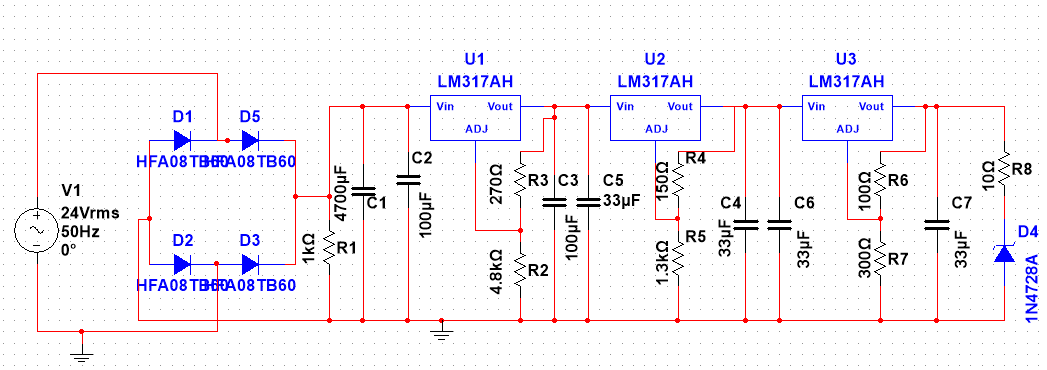
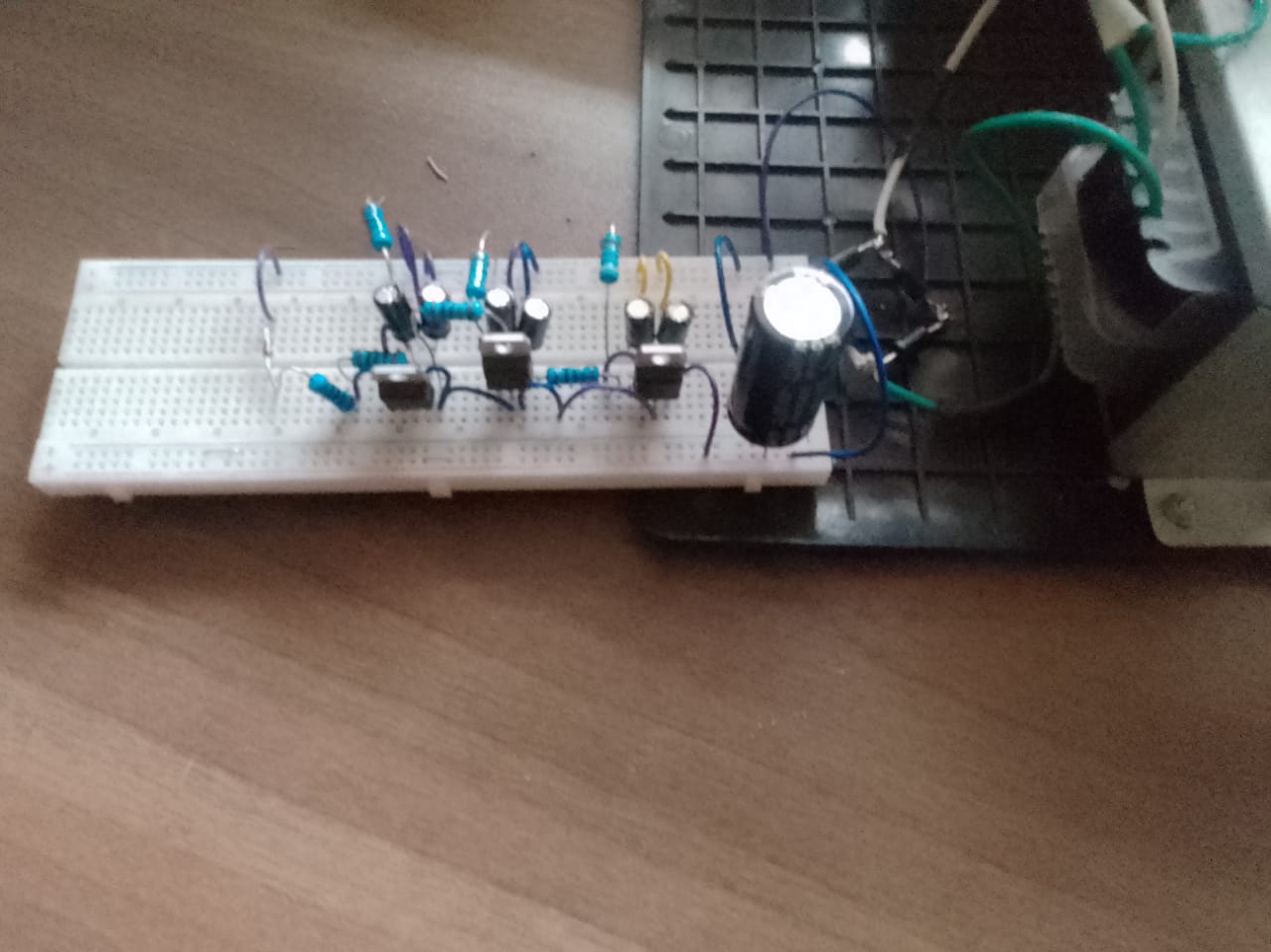
Multisim and Bench Circuit Diagram
Figure 1 and Figure 2 below illustrate the simulated and physical circuit respectively.
Transformer Stage, Voltage Step-Down
Transformer Specifications:
- Type: EI-76X45
- Output: 24-0-24V AC, 5A, 50Hz
A center-tapped step-down transformer converts the 220V AC mains to 24 V AC. This center-tap configuration is a common method for achieving full-wave rectification, especially at higher voltages. The peak voltage after rectification reaches approximately 34V. This provides sufficient headroom for voltage regulation down to 24 V, 12 V, 5 V, and 3.3 V while ensuring continuous operation at up to 1 A per output rail.
Simulation Output
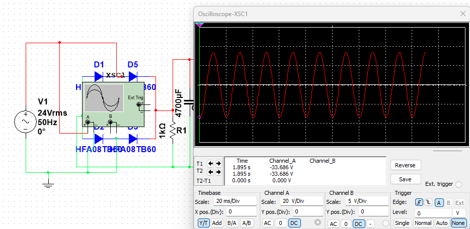
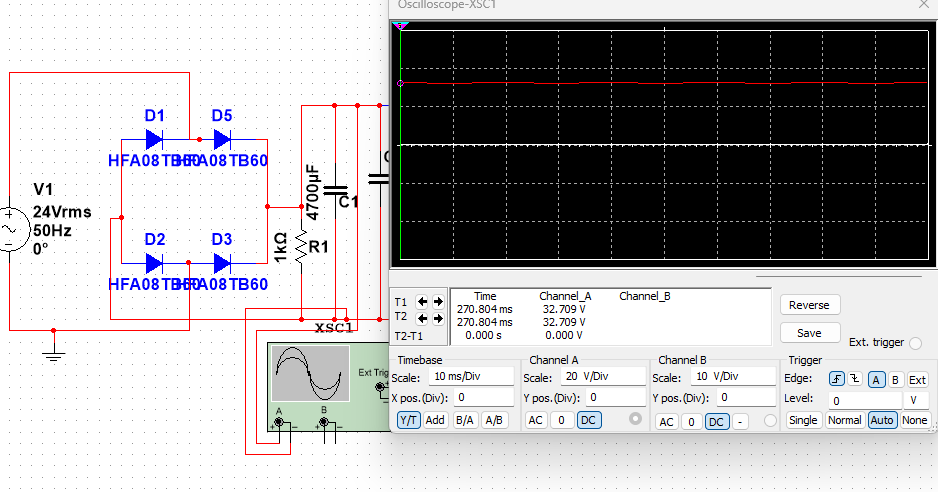
Rectification Stage, AC to DC Conversion
A full-wave bridge rectifier using four HER307 high-speed diodes (D1-D4) converts the AC voltage into pulsating DC. The diodes have the following specifications:
- Average Forward Current: 3A
- Peak Reverse Voltage: 1000V
- Fast Recovery Time
Refer to : alldatasheet-HER307 for more details.
Peak Voltage Calculation
Accounting for two diode drops (~1.4V):
Simulation Output
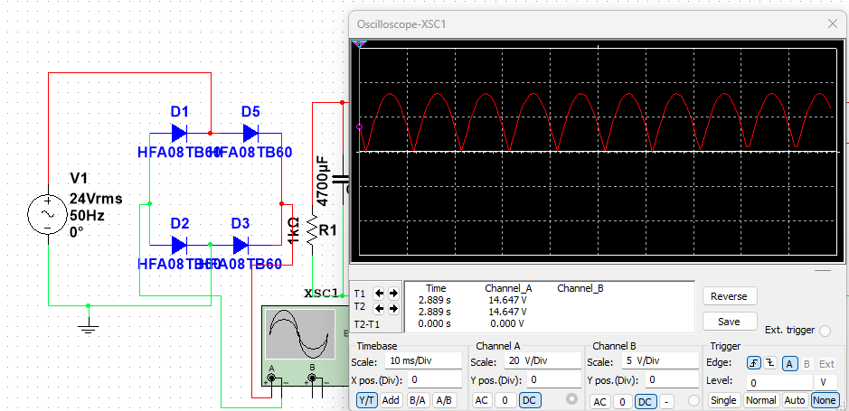
Filtering Stage, Ripple Reduction
Bulk Filtering: A 4700μF, 50V electrolytic capacitor is used to smooth the rectified voltage and reduce ripple.
Additional Capacitors: Smaller capacitors (100μF, 33μF) placed after each regulator further suppress high-frequency noise and improve transient response.
Simulation Output
Voltage Regulation Stage, LM317T Adjustable Regulators
The LM317T is a 3-terminal adjustable regulator capable of supplying 1.2V to 37V at up to 1.5A. In this design, each regulated output is configured for a maximum load current of 1 A, ensuring thermal and electrical reliability within device limits.
Refer to:alldatasheet-LM317T for details.
Why LM317T Instead of 78XX Series?
While fixed-voltage regulators like the 7805 or 7812 are convenient, the LM317T offers key advantages in this application:
- Adjustability: A single regulator can be configured for multiple voltages using external resistors.
- Greater flexibility: Ideal for custom or non-standard voltage rails.
- Improved line and load regulation: Superior transient response and output accuracy with proper bypassing.
- Availability and cost: Readily available and cost-effective for educational and prototyping purposes.
Output Voltage Formula:
24V Output (U1)
- R1 = 1kΩ, R2 = 18.2kΩ
- Applicable in; Powering relays, motor drivers, audio amplifiers
- Capacitors: 300μF and 33μF
12V Output (U2)
- R1 = 1kΩ, R2 = 8.6kΩ
- Common applications include; powering logic circuits, operational amplifiers, and development boards
5V Output (U3)
- R1 = 240Ω, R2 = 720Ω
- Applicable in; Microcontrollers, USB-powered devices
3.3V Zener Clamp
A 1N4728A Zener diode clamps the 5V rail to 3.3V for low-current applications.
- Zener Voltage: 3.3V
- Power Rating: 1W
- Series resistor (10Ω) limits current
Note: Zener diodes are not efficient for high-current regulation; use only for low-power logic or reference lines.Refer to: alldatasheet-1N4728A for more details.
Thermal and Safety Considerations
- Heat Dissipation: LM317s can dissipate significant heat. For example: Use heat sinks accordingly.
- Enclosure: Use a ventilated metal or plastic enclosure.
- Fusing: Place fuses or PTC resettable fuses after the transformer.
- Isolation: Ensure the transformer provides safe mains isolation.
Applications
This multi-output power supply is:
- Ideal for educational electronics labs
- Simple and low-cost to build
- Versatile for powering multiple circuit types
Typical Use Cases:
- Microcontroller prototyping
- Powering 5V/12V modules simultaneously
- Audio circuits with 24V rails
- Logic-level shifting or analog reference supply
References
Keep Reading
Related Articles
Comments
Sign in to join the discussion.
Loading comments…